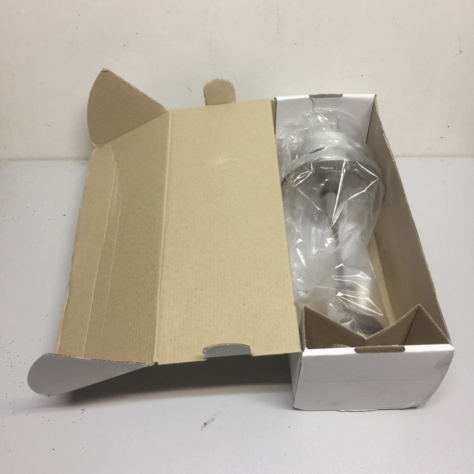
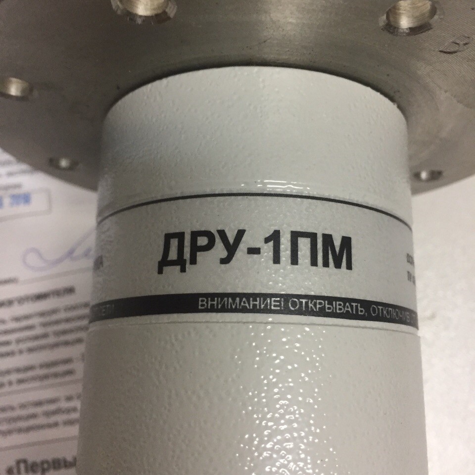
DRU-1PM sensor
DRU-1PM two-position float-type level sensor-switch is used to control the upper or lower level of water, oils, diesel fuel, coolants and other liquids in automation systems of industrial facilities, tank farms, storage facilities for fuels and lubricants, in the automation of sea or river vessels.
Two-position liquid level switch sensors DRU-1PM, DRU-1PM-1, DRU-1 are designed to control the upper or lower level of fresh water with chromium peak, oils, low-freezing coolant, fecal liquid, diesel fuel. Sensors-relays are intended for use in automatic control circuits of diesel-electric units, and can also be used in stationary conditions. The device can be used to control the level of other liquids that are non-aggressive towards steel grade 08X18H10T and alloy 36NKHTYu, viscosity no more than 2000 cS and density from 0.8 103 to 1.2 103 kg / m3.
DRU -1PM technical characteristics:
Operation differential no more than 25 mm.
• Working pressure from 0.054 to 0.2 MPa.
• Operation error DRU-1PM - no more than 12.5 mm relative to the nominal response level.
Corrosion-resistant design.
Dust and moisture protection degree IP 54.
DRU-1PM installation rules
Attention!
To avoid crushing the sensitive element (bellows), handle the sensor - the relay should be installed carefully. Before mounting the sensor-relay, move the locking device screw from the position for transportation to the position for operation, for which:
1) remove the cover;
2) turn the screw counterclockwise by 180 ° (the index on the screw head must be opposite letters "Э" on the body;
3) check the actuation of the contacts of the microswitch DRU-1PM by slowly lowering and raising the float in the vertical plane passing through the letters "В" - "Н" on the flange (the moment of switching is determined by the "click" of the spring microswitch);
4) fix the cover, ensuring a seal, and seal.
The DRU-1PM level switch is installed on a tank with a controlled medium so that the flange of the device body is in a vertical position: deviation from the vertical not more than ± 1 °, and the deviation of the axis passing through the upper and lower mounting holes from the vertical did not exceed ± 1.5 °. When checking the upper level, the letter "B" should be on the top of the flange of the device body, and when checking the lower level - the letter "H". The plug connectors are designed for shielded cables and can be connected to 2.5 mm2 conductors. The cable cores must be connected to the socket outlet according to the "Electrical Connection Diagram". After connection, the socket of the connector must be secured with a wire.


